If you are experiencing DM32X network connection issues, or see a “limited connectivity” message, The FAQ linked below can help.
The DM32X Internet connectivity can be impacted by a low battery. The best first step is to charge your gauge back to full battery and retest. This often takes care of the issue.
It is also recommended to make sure the feature ‘Battery Saver’ is disabled. The guide below will walk you through these steps, as well as steps to confirm the gauge has a valid IP address and internet connectivity.
Unfortunately no, any kind of dye in the fluid will clog the vaporizer. It will also stain the room being smoked as the dye wont vaporize.
If you are having issues seeing the smoke, more light in the room will help you trace it. Also remember that higher pressure differentials will increase the smoke movement. Lower pressures will slow the smoke movement down.
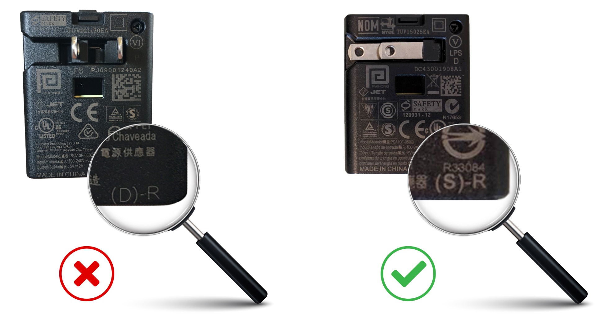
Please check Retrotec USB chargers for the marking shown in the below image.
Please contact support@retrotec.com if your gauge isn’t working for any other reason, as well.
The main disadvantage to positive duct test pressure is that it blows off register seals or makes them leak. An LBL study showed a wide dispersion of results when the same duct test was repeated many times. Depressurizing will allow the use of lower sticking masking materials that are less likely to pull off the paint. In some cases plastic food wrap will work.
The main advantage to positive duct test pressure is that the flex duct doesn’t contract as much. In cases where the flex runs to the ceiling this contraction effect might cause problems.
Testing using depressurization will usually result in less leakage because gaps and seams will be pulled closed”
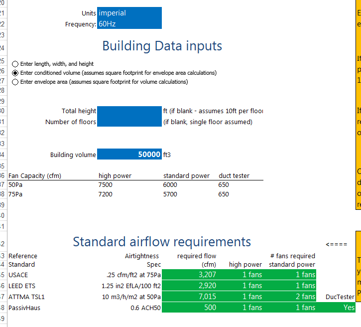
I have a Energy or Enclosure Integrity Test to perform. How many fans do I need to properly run the test? Do I have enough fans to run the test?
We have created two tools to help you figure out how many fans you will need for your test.
Download either the Blower Door or Enclosure Integrity version of the Number of Fans Calculator.
Next, open the file in excel and “Enable Editing” when a security warning appears.
Fill in all the fields highlighted in blue. The number of fan results are highlighted in green.
Here is what the Blower Door Number of Fans Calculator looks like:
And this is what the Enclosure Integrity version of the Number of Fans calculator looks like:

Note that these tools are only approximations and only serve as a guide.
If this is the Error you are seeing:

Click on the “Details” button to get more information. In the summary, you will see:
ERROR SUMMARY: “+ Your Web browser settings do not allow you to run signed applications.”
This error summary indicates that there are security settings in your web browser that are preventing the application from being able to download.
Some people have had success by adding http://retrotec.com to their “Trusted Sites” in the Tools>>Internet Options>>Security settings window in Internet Explorer:

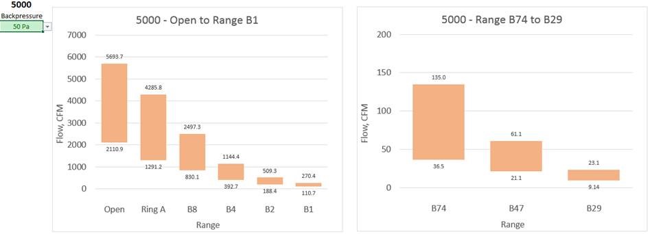
5000 Flow test
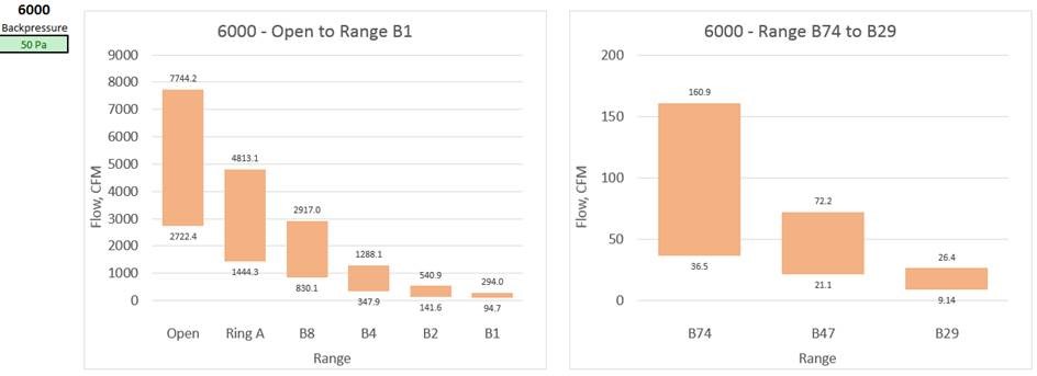
6000 Flow test
Fan Pressure (flow pressure) is too low for the Range, which means you should change to a smaller more restrictive Range to increase fan pressure.
Click the “Reset to Standard Default” button in the Advanced settings menu, to ensure default program parameters are used.
The L ranges on the fan are designed to be left open unless you are using L2 or L1.
Covering those four 1 inch holes in the center of the C8 plate will cause range C1 to read about 25% higher and C2 to read about 12% higher flow.
Our manufacturer’s recommendation for calibration is as follows:
- Retrotec fans: Every 5 years.
- DM-2 Manometer: Every 2 years or if the Manometer fails a field check.
- DM32 / DM32 WiFi Manometer: Every 5 years or if the Manometer fails a field check.
Please review the DM32 and DM-2 Manuals on how to perform a field check.
This only covers our manufacturer recommendation. The energy standards (EN13829, ASTM, ATTMA, USACE, etc…) that you are using for test results may have different calibration intervals. Please consult the energy standards for the specific equipment calibration intervals.
L
Retrotec recommends you take the maximum number of test points to decrease the uncertainty in your test.
Yes, you can change this default and take only 5 readings according to the Standard but your uncertainty will often be too high and you might have to retest. Next, you might retest and find the result differs from the previous test by 10% or more making you lose confidence in the results. Retrotec defaults that include taking 10 test points and longer baselines will optimize your tests and give better results.
You might save a few minutes by testing to the minimum allowed by the Standards but in the long run, your test results will be poor. Officials look at high uncertainties and poor repeatabilities between your tests and wrongly conclude your equipment is faulty but the truth is that your test method is faulty. Please use our defaults as practical minimums and if anything take your tests over a longer time rather than shorter and your results will be vastly improved. As a rule when you take tests over a time period that is four times longer, your errors are reduced by half.
*Max current is initial in-rush current. Generators used for Retrotec equipment should be inverter type generators, (i.e., suitable for use with sensitive electronics).
| Voltage (VAC) | Max current (A) | Power (W) | |
| 3000 (3 Phase Drive) | 120 | 22 | 2640 |
| 208 | 13 | 2704 | |
| 230 | 10.5 | 2415 | |
| 240 | 10.3 | 2472 | |
***** Minimum generator power output should be 3000W ***** | |||
| 1000 Calibrated Fan | 120 | 23 | 2760 |
| 208 | 11 | 2288 | |
***** Minimum generator power output should be 3000W ***** | |||
In order to do both, you need to be sure you have version 5.8.30 of FanTestic or later.
In all versions of FanTestic before version 5.8.30, if you plugged a DM32 into a computer USB to give it power (instead of plugging into the wall adapter) FanTestic would assume you also wanted to use USB Serial connection for control. FanTestic made this assumption even if the gauge was also connected to the computer over Ethernet (via the Network cable or via WiFi).
In all versions starting with 5.8.30, FanTestic discovers gauges connected via Ethernet first, so it can ignore the same gauge also found on USB Serial.
This change allows users to have their DM32 connected for control via Ethernet but also connect the DM32 to the computer USB port for power (if it is more convenient than connecting to a wall outlet). Retrotec recommends that users use Ethernet connection rather than USB for controlling the DM32.
I am doing duct testing and use the DW/143 standard (UK). FanTestic keeps telling me the test is not compliant, what am I doing wrong?
FanTestic checks that you have held the ducts at the test pressure for at least 900 seconds. If you do not, the test will show as not compliant. If you did a manual test and are entering the information into FanTestic, be sure to enter the time over which the test pressure was held. If this is greater than 900 and your other test conditions are correct, the test will show compliant.
Compliance means the test conditions comply with the stated requirements for a test in DW/143. Pass or fail means that the measured results are within the required level.
The big issue is exhaust getting into the house. Duct leaks from the supply side cause the house to have a negative pressure, which can cause air to get pulled in from the garage. Exhaust entering the home can be dangerous and can lead to health issues.
The first step is to find what the maximum house depressurization would be with combinations of the airhandler on, closed bedroom doors, and any exhaust fans running. Do what you can to eliminate these pressures. Check to make sure there aren’t any air intakes (returns) inside the garage.
To determine how leaky the garage to house connection is test the house leakage at 50 Pa, then pressurize the garage to 50 Pa; if you see any drop in flow, there’s a connection between the two.
Next, depressurize the house and use a smoke puffer to test the garage to house connection. Seal everything between these two zones.
Modular Panels are designed to be placed into doors that are not well sealed. The panel leakage for the Modular Panel is about 14 square inches compared to about 3 square inches for the Aluminum Frame and Cloth and around 1 square inch of leakage for the upgraded Aluminum Frame with snap together corners. These three panels represent three typical doorways:
- Poorly weather-stripped which would have an approximate 1/16 inch gap which equals about 14 square inches leakage;
- A well weather-stripped and adjusted door would be around 3 square inches or leakage;
- A super tight door could be as tight as 1 square inch of leakage and can even have less.
One rule of thumb is that all standards require the blower door panel to be leakier and never tighter than the existing door. The Modular Panel qualifies here. It is likely that the Aluminum Frame and Cloth are tighter than the existing door. In either case, if the door panel leakage is 10% of the total, then further investigation is needed.
Modular Panels:
1000 CFM at 50 Pa, no attention needs to be paid to the door panel leakage. If the flow rate is under that you might want to measure the panel tightness compared to the door tightness and subtract any excess from the readings. Or, if the panel is tighter than the door, you will have to add it.
Example; 500 CFM at 50 Pa for the enclosure. Door is closed over top of the panel with the red tube in the gap and leakage measured at 50 Pa of 140 CFM. The door is then taped shut to measure panel leakage which is 80 CFM at 50 Pa. The Door thus leaks 140-80=60 CFM. Correction to test result is then: 500-80+60= 480 CFM.
Aluminum Frame and Cloth:
220 CFM at 50 Pa, no attention needs to be paid to the door panel leakage.
Aluminum Frame with upgraded snap together corners and Cloth:
70 CFM at 50 Pa, no attention needs to be paid to the door panel leakage. If the flow rate is under that you should measure the panel tightness compared to the door tightness and subtract any excess from the readings. Or, if the panel is tighter than the door, you will have to add it which is more common and shown in the following example:
Example: 50 CFM at 50 Pa for the enclosure. Door is closed over top of the panel with the red tube in the gap and leakage measured at 50 Pa of 8 CFM. The door is then taped shut to measure panel leakage which is 3 CFM at 50 Pa. The Door then leaks 8-3= 5 CFM. Correction to test result is thus: 50-3+5= 52 CFM.
These tests are rarely done but testers should learn how leaky their panels are in advance of any test they may do. Retrotec has performed this test in nuclear power plants where every part of the test needed to be documented including panel leaks. Learning how much your panels leak will be a useful tool to determine how they might be affecting your results. For example, when Modular Panels are used to measure flows well in excess of 2000 CFM, the panel leakage is irrelevant, but in tight rooms it could make the difference between pass or fail. One has to determine then if the door leakage may be a major part of the total and cannot just be deducted. Similarly, if you are using the new tight Aluminum Frame with square snap together corners, your readings might be low.
The exterior pressure reference for the differential pressure measurement across the door panel is provided by the red tube. The exterior pickup location must be chosen to minimize the influence of wind, sun and atmospheric pressure on the differential measurement, or measurements must be taken to allow correction for these influences. Each standard defines what is expected in terms of the exterior reference pressure measurement. Use Table 2 to determine where best to locate your red tube depending on the standard procedure you are following.
Table 2: Locations for Exterior Reference Pressure Pickup as required by the various Standard Procedures
| Exterior pressure pick-up locations from Standards | |
| ASTM | 1 tube across the middle of each façade (NOT at corners of the building) |
| Manifold and average all pressure readings using a manifold (averaged ver 10s) | |
| If > 3 stories, measured at more than 1 height | |
| ATTMA | Measured at the lowest floor level of the building |
| Located “some distance away” from the building envelope, out of the way of fan airflow and sheltered from wind | |
| CGSB | Calm conditions – 1 pressure measurement outside the building is ok |
| Windy – min of 4 measurements on each façade, manifold | |
| Gusty winds – use wind damping kit (capillary tubes, averaged over 5s) | |
| EN13829-FR | Measure at the bottom floor level, but if tall building, measure at the top as well |
| Keep exterior pressure taps out of the sun, and fitted to a T-pipe or connected to a perforated box to protect from wind | |
| USACE | Min 1 exterior pressure tap required, but if bias pressures high, use more |
Interior pressure gauge references tied together in a manifold to read 1 pressure reading |
Figure 28 typically recommended locations for exterior pressure pickups
Even though most standards recommend pressure pickup placement as shown above, this is seldom done because the fluctuations are not large enough to warrant the time. In fact, results may be improved by multiple pickups or in some cases may be made worse. Sometimes one exterior pickup is sufficient.
See section 5.8 “Enclosure pressure measurement disturbances” for more details on how to avoid pressure fluctuations.
5.8 Enclosure pressure measurement disturbances
Induced enclosure pressures are the difference between outdoors and inside the measured zone. The outdoor pressure pickup point(s) will be affected by wind. Steady winds create pressure that can be subtracted from readings but wind is never steady and it’s the fluctuations that cause problems. Generally, on the windward side of the building impacts the ends of pressure tubes creating a positive pressure due to the wind velocity being stopped by the tube. Positive pressures will also result from the overall air movement being stopped by the windward side of the building creating a positive pressure field that can extend 5 to 20 feet from the building. To overcome these effects, it is best to use pickup point(s) away from the direct impact of wind.
The impact of the wind can be best measured by the effect on the gauge. First, extend the exterior pressure pickup point of the tube away from the fan’s airstream and about 5 feet from the building. Monitor the gauge for ten minutes. If the gauge reading is above 2 Pa, insert a T in the tube end and cover the tube end with a flat sheet. If still above 2 Pa, T the tube and add two equal length tubes sufficient to be placed in two wind free locations on opposite sides of the building. It may be necessary to T these tubes once more to create 4 pressure pickup points, again with equal length tubes.
Ensure the tube ends are not in contact with water since that will seal them off.
Red tubes are always run through the Door Panel and connected to the Red port on the gauge. If testing from inside the building, red tubes will be run outdoors. If testing from outside the building, a red tube runs through the panel but Blue tubes are used to pick up the outdoor pressure. This is done to ensure, the gauge always reads the pressure in the building with the correct sign, namely, if the building is being depressurized, the gauges will read negative. If pressurized, the gauges will read positive. This works whether the tester and gauges are indoors or outdoors.
Passing more than one tube through the enclosure is possible and an approach that is sometimes used but in general there is seldom an advantage to doing this. As long as the exterior pressure pickup used is in a favorable location, it will adequately represent the outdoor pressure since the outdoor pressure will be unaffected by the test fans since outdoors is an unlimited sink for airflow just like it is when for the grounding of electrical circuits.
Running multiple blue tubes indoors is important because we must ensure all areas in the zone have similar test pressures.
I have a Energy or Enclosure Integrity Test to perform. How many fans do I need to properly run the test? Do I have enough fans to run the test?
We have created two tools to help you figure out how many fans you will need for your test.
Download either the Blower Door or Enclosure Integrity version of the Number of Fans Calculator.
Next, open the file in excel and “Enable Editing” when a security warning appears.
Fill in all the fields highlighted in blue. The number of fan results are highlighted in green.
Here is what the Blower Door Number of Fans Calculator looks like:
And this is what the Enclosure Integrity version of the Number of Fans calculator looks like:
Note that these tools are only approximations and only serve as a guide.
Modular Panels are designed to be placed into doors that are not well sealed. The panel leakage for the Modular Panel is about 14 square inches compared to about 3 square inches for the Aluminum Frame and Cloth and around 1 square inch of leakage for the upgraded Aluminum Frame with snap together corners. These three panels represent three typical doorways:
- Poorly weather-stripped which would have an approximate 1/16 inch gap which equals about 14 square inches leakage;
- A well weather-stripped and adjusted door would be around 3 square inches or leakage;
- A super tight door could be as tight as 1 square inch of leakage and can even have less.
One rule of thumb is that all standards require the blower door panel to be leakier and never tighter than the existing door. The Modular Panel qualifies here. It is likely that the Aluminum Frame and Cloth are tighter than the existing door. In either case, if the door panel leakage is 10% of the total, then further investigation is needed.
Modular Panels:
1000 CFM at 50 Pa, no attention needs to be paid to the door panel leakage. If the flow rate is under that you might want to measure the panel tightness compared to the door tightness and subtract any excess from the readings. Or, if the panel is tighter than the door, you will have to add it.
Example; 500 CFM at 50 Pa for the enclosure. Door is closed over top of the panel with the red tube in the gap and leakage measured at 50 Pa of 140 CFM. The door is then taped shut to measure panel leakage which is 80 CFM at 50 Pa. The Door thus leaks 140-80=60 CFM. Correction to test result is then: 500-80+60= 480 CFM.
Aluminum Frame and Cloth:
220 CFM at 50 Pa, no attention needs to be paid to the door panel leakage.
Aluminum Frame with upgraded snap together corners and Cloth:
70 CFM at 50 Pa, no attention needs to be paid to the door panel leakage. If the flow rate is under that you should measure the panel tightness compared to the door tightness and subtract any excess from the readings. Or, if the panel is tighter than the door, you will have to add it which is more common and shown in the following example:
Example: 50 CFM at 50 Pa for the enclosure. Door is closed over top of the panel with the red tube in the gap and leakage measured at 50 Pa of 8 CFM. The door is then taped shut to measure panel leakage which is 3 CFM at 50 Pa. The Door then leaks 8-3= 5 CFM. Correction to test result is thus: 50-3+5= 52 CFM.
These tests are rarely done but testers should learn how leaky their panels are in advance of any test they may do. Retrotec has performed this test in nuclear power plants where every part of the test needed to be documented including panel leaks. Learning how much your panels leak will be a useful tool to determine how they might be affecting your results. For example, when Modular Panels are used to measure flows well in excess of 2000 CFM, the panel leakage is irrelevant, but in tight rooms it could make the difference between pass or fail. One has to determine then if the door leakage may be a major part of the total and cannot just be deducted. Similarly, if you are using the new tight Aluminum Frame with square snap together corners, your readings might be low.
5000 Flowchart
6000 Flowchart
Fan Pressure (flow pressure) is too low for the Range, which means you should change to a smaller more restrictive Range to increase fan pressure.
If this is the Error you are seeing:
Click on the “Details” button to get more information. In the summary, you will see:
ERROR SUMMARY: “+ Your Web browser settings do not allow you to run signed applications.”
This error summary indicates that there are security settings in your web browser that are preventing the application from being able to download.
Some people have had success by adding http://retrotec.com to their “Trusted Sites” in the Tools>>Internet Options>>Security settings window in Internet Explorer:
Our manufacturer’s recommendation for calibration is as follows:
- Retrotec fans: Every 5 years.
- DM-2 Manometer: Every 2 years or if the Manometer fails a field check.
- DM32 / DM32 WiFi Manometer: Every 5 years or if the Manometer fails a field check.
Please review the DM32 and DM-2 Manuals on how to perform a field check.
This only covers our manufacturer recommendation. The energy standards (EN13829, ASTM, ATTMA, USACE, etc…) that you are using for test results may have different calibration intervals. Please consult the energy standards for the specific equipment calibration intervals.
Click the “Reset to Standard Default” button in the Advanced settings menu, to ensure default program parameters are used.
Retrotec recommends you take the maximum number of test points to decrease the uncertainty in your test.
Yes, you can change this default and take only 5 readings according to the Standard but your uncertainty will often be too high and you might have to retest. Next, you might retest and find the result differs from the previous test by 10% or more making you lose confidence in the results. Retrotec defaults that include taking 10 test points and longer baselines will optimize your tests and give better results.
You might save a few minutes by testing to the minimum allowed by the Standards but in the long run, your test results will be poor. Officials look at high uncertainties and poor repeatabilities between your tests and wrongly conclude your equipment is faulty but the truth is that your test method is faulty. Please use our defaults as practical minimums and if anything take your tests over a longer time rather than shorter and your results will be vastly improved. As a rule when you take tests over a time period that is four times longer, your errors are reduced by half.
In order to do both, you need to be sure you have version 5.8.30 of FanTestic or later.
In all versions of FanTestic before version 5.8.30, if you plugged a DM32 into a computer USB to give it power (instead of plugging into the wall adapter) FanTestic would assume you also wanted to use USB Serial connection for control. FanTestic made this assumption even if the gauge was also connected to the computer over Ethernet (via the Network cable or via WiFi).
In all versions starting with 5.8.30, FanTestic discovers gauges connected via Ethernet first, so it can ignore the same gauge also found on USB Serial.
This change allows users to have their DM32 connected for control via Ethernet but also connect the DM32 to the computer USB port for power (if it is more convenient than connecting to a wall outlet). Retrotec recommends that users use Ethernet connection rather than USB for controlling the DM32.
I am doing duct testing and use the DW/143 standard (UK). FanTestic keeps telling me the test is not compliant, what am I doing wrong?
FanTestic checks that you have held the ducts at the test pressure for at least 900 seconds. If you do not, the test will show as not compliant. If you did a manual test and are entering the information into FanTestic, be sure to enter the time over which the test pressure was held. If this is greater than 900 and your other test conditions are correct, the test will show compliant.
Compliance means the test conditions comply with the stated requirements for a test in DW/143. Pass or fail means that the measured results are within the required level.
Modular Panels are designed to be placed into doors that are not well sealed. The panel leakage for the Modular Panel is about 14 square inches compared to about 3 square inches for the Aluminum Frame and Cloth and around 1 square inch of leakage for the upgraded Aluminum Frame with snap together corners. These three panels represent three typical doorways:
- Poorly weather-stripped which would have an approximate 1/16 inch gap which equals about 14 square inches leakage;
- A well weather-stripped and adjusted door would be around 3 square inches or leakage;
- A super tight door could be as tight as 1 square inch of leakage and can even have less.
One rule of thumb is that all standards require the blower door panel to be leakier and never tighter than the existing door. The Modular Panel qualifies here. It is likely that the Aluminum Frame and Cloth are tighter than the existing door. In either case, if the door panel leakage is 10% of the total, then further investigation is needed.
Modular Panels:
1000 CFM at 50 Pa, no attention needs to be paid to the door panel leakage. If the flow rate is under that you might want to measure the panel tightness compared to the door tightness and subtract any excess from the readings. Or, if the panel is tighter than the door, you will have to add it.
Example; 500 CFM at 50 Pa for the enclosure. Door is closed over top of the panel with the red tube in the gap and leakage measured at 50 Pa of 140 CFM. The door is then taped shut to measure panel leakage which is 80 CFM at 50 Pa. The Door thus leaks 140-80=60 CFM. Correction to test result is then: 500-80+60= 480 CFM.
Aluminum Frame and Cloth:
220 CFM at 50 Pa, no attention needs to be paid to the door panel leakage.
Aluminum Frame with upgraded snap together corners and Cloth:
70 CFM at 50 Pa, no attention needs to be paid to the door panel leakage. If the flow rate is under that you should measure the panel tightness compared to the door tightness and subtract any excess from the readings. Or, if the panel is tighter than the door, you will have to add it which is more common and shown in the following example:
Example: 50 CFM at 50 Pa for the enclosure. Door is closed over top of the panel with the red tube in the gap and leakage measured at 50 Pa of 8 CFM. The door is then taped shut to measure panel leakage which is 3 CFM at 50 Pa. The Door then leaks 8-3= 5 CFM. Correction to test result is thus: 50-3+5= 52 CFM.
These tests are rarely done but testers should learn how leaky their panels are in advance of any test they may do. Retrotec has performed this test in nuclear power plants where every part of the test needed to be documented including panel leaks. Learning how much your panels leak will be a useful tool to determine how they might be affecting your results. For example, when Modular Panels are used to measure flows well in excess of 2000 CFM, the panel leakage is irrelevant, but in tight rooms it could make the difference between pass or fail. One has to determine then if the door leakage may be a major part of the total and cannot just be deducted. Similarly, if you are using the new tight Aluminum Frame with square snap together corners, your readings might be low.
The exterior pressure reference for the differential pressure measurement across the door panel is provided by the red tube. The exterior pickup location must be chosen to minimize the influence of wind, sun and atmospheric pressure on the differential measurement, or measurements must be taken to allow correction for these influences. Each standard defines what is expected in terms of the exterior reference pressure measurement. Use Table 2 to determine where best to locate your red tube depending on the standard procedure you are following.
Table 2: Locations for Exterior Reference Pressure Pickup as required by the various Standard Procedures
| Exterior pressure pick-up locations from Standards | |
| ASTM | 1 tube across the middle of each façade (NOT at corners of the building) |
| Manifold and average all pressure readings using a manifold (averaged ver 10s) | |
| If > 3 stories, measured at more than 1 height | |
| ATTMA | Measured at the lowest floor level of the building |
| Located “some distance away” from the building envelope, out of the way of fan airflow and sheltered from wind | |
| CGSB | Calm conditions – 1 pressure measurement outside the building is ok |
| Windy – min of 4 measurements on each façade, manifold | |
| Gusty winds – use wind damping kit (capillary tubes, averaged over 5s) | |
| EN13829-FR | Measure at the bottom floor level, but if tall building, measure at the top as well |
| Keep exterior pressure taps out of the sun, and fitted to a T-pipe or connected to a perforated box to protect from wind | |
| USACE | Min 1 exterior pressure tap required, but if bias pressures high, use more |
| Interior pressure gauge references tied together in a manifold to read 1 pressure reading |
Figure 28 typically recommended locations for exterior pressure pickups
Even though most standards recommend pressure pickup placement as shown above, this is seldom done because the fluctuations are not large enough to warrant the time. In fact, results may be improved by multiple pickups or in some cases may be made worse. Sometimes one exterior pickup is sufficient.
See section 5.8 “Enclosure pressure measurement disturbances” for more details on how to avoid pressure fluctuations.
5.8 Enclosure pressure measurement disturbances
Induced enclosure pressures are the difference between outdoors and inside the measured zone. The outdoor pressure pickup point(s) will be affected by wind. Steady winds create pressure that can be subtracted from readings but wind is never steady and it’s the fluctuations that cause problems. Generally, on the windward side of the building impacts the ends of pressure tubes creating a positive pressure due to the wind velocity being stopped by the tube. Positive pressures will also result from the overall air movement being stopped by the windward side of the building creating a positive pressure field that can extend 5 to 20 feet from the building. To overcome these effects, it is best to use pickup point(s) away from the direct impact of wind.
The impact of the wind can be best measured by the effect on the gauge. First, extend the exterior pressure pickup point of the tube away from the fan’s airstream and about 5 feet from the building. Monitor the gauge for ten minutes. If the gauge reading is above 2 Pa, insert a T in the tube end and cover the tube end with a flat sheet. If still above 2 Pa, T the tube and add two equal length tubes sufficient to be placed in two wind free locations on opposite sides of the building. It may be necessary to T these tubes once more to create 4 pressure pickup points, again with equal length tubes.
Ensure the tube ends are not in contact with water since that will seal them off.
Red tubes are always run through the Door Panel and connected to the Red port on the gauge. If testing from inside the building, red tubes will be run outdoors. If testing from outside the building, a red tube runs through the panel but Blue tubes are used to pick up the outdoor pressure. This is done to ensure, the gauge always reads the pressure in the building with the correct sign, namely, if the building is being depressurized, the gauges will read negative. If pressurized, the gauges will read positive. This works whether the tester and gauges are indoors or outdoors.
Passing more than one tube through the enclosure is possible and an approach that is sometimes used but in general there is seldom an advantage to doing this. As long as the exterior pressure pickup used is in a favorable location, it will adequately represent the outdoor pressure since the outdoor pressure will be unaffected by the test fans since outdoors is an unlimited sink for airflow just like it is when for the grounding of electrical circuits.
Running multiple blue tubes indoors is important because we must ensure all areas in the zone have similar test pressures.
I have a Energy or Enclosure Integrity Test to perform. How many fans do I need to properly run the test? Do I have enough fans to run the test?
We have created two tools to help you figure out how many fans you will need for your test.
Download either the Blower Door or Enclosure Integrity version of the Number of Fans Calculator.
Next, open the file in excel and “Enable Editing” when a security warning appears.
Fill in all the fields highlighted in blue. The number of fan results are highlighted in green.
Here is what the Blower Door Number of Fans Calculator looks like:
And this is what the Enclosure Integrity version of the Number of Fans calculator looks like:
Note that these tools are only approximations and only serve as a guide.
I have a Energy or Enclosure Integrity Test to perform. How many fans do I need to properly run the test? Do I have enough fans to run the test?
We have created two tools to help you figure out how many fans you will need for your test.
Download either the Blower Door or Enclosure Integrity version of the Number of Fans Calculator.
Next, open the file in excel and “Enable Editing” when a security warning appears.
Fill in all the fields highlighted in blue. The number of fan results are highlighted in green.
Here is what the Blower Door Number of Fans Calculator looks like:
And this is what the Enclosure Integrity version of the Number of Fans calculator looks like:
Note that these tools are only approximations and only serve as a guide.
Modular Panels are designed to be placed into doors that are not well sealed. The panel leakage for the Modular Panel is about 14 square inches compared to about 3 square inches for the Aluminum Frame and Cloth and around 1 square inch of leakage for the upgraded Aluminum Frame with snap together corners. These three panels represent three typical doorways:
- Poorly weather-stripped which would have an approximate 1/16 inch gap which equals about 14 square inches leakage;
- A well weather-stripped and adjusted door would be around 3 square inches or leakage;
- A super tight door could be as tight as 1 square inch of leakage and can even have less.
One rule of thumb is that all standards require the blower door panel to be leakier and never tighter than the existing door. The Modular Panel qualifies here. It is likely that the Aluminum Frame and Cloth are tighter than the existing door. In either case, if the door panel leakage is 10% of the total, then further investigation is needed.
Modular Panels:
1000 CFM at 50 Pa, no attention needs to be paid to the door panel leakage. If the flow rate is under that you might want to measure the panel tightness compared to the door tightness and subtract any excess from the readings. Or, if the panel is tighter than the door, you will have to add it.
Example; 500 CFM at 50 Pa for the enclosure. Door is closed over top of the panel with the red tube in the gap and leakage measured at 50 Pa of 140 CFM. The door is then taped shut to measure panel leakage which is 80 CFM at 50 Pa. The Door thus leaks 140-80=60 CFM. Correction to test result is then: 500-80+60= 480 CFM.
Aluminum Frame and Cloth:
220 CFM at 50 Pa, no attention needs to be paid to the door panel leakage.
Aluminum Frame with upgraded snap together corners and Cloth:
70 CFM at 50 Pa, no attention needs to be paid to the door panel leakage. If the flow rate is under that you should measure the panel tightness compared to the door tightness and subtract any excess from the readings. Or, if the panel is tighter than the door, you will have to add it which is more common and shown in the following example:
Example: 50 CFM at 50 Pa for the enclosure. Door is closed over top of the panel with the red tube in the gap and leakage measured at 50 Pa of 8 CFM. The door is then taped shut to measure panel leakage which is 3 CFM at 50 Pa. The Door then leaks 8-3= 5 CFM. Correction to test result is thus: 50-3+5= 52 CFM.
These tests are rarely done but testers should learn how leaky their panels are in advance of any test they may do. Retrotec has performed this test in nuclear power plants where every part of the test needed to be documented including panel leaks. Learning how much your panels leak will be a useful tool to determine how they might be affecting your results. For example, when Modular Panels are used to measure flows well in excess of 2000 CFM, the panel leakage is irrelevant, but in tight rooms it could make the difference between pass or fail. One has to determine then if the door leakage may be a major part of the total and cannot just be deducted. Similarly, if you are using the new tight Aluminum Frame with square snap together corners, your readings might be low.
Fan Pressure (flow pressure) is too low for the Range, which means you should change to a smaller more restrictive Range to increase fan pressure.
If this is the Error you are seeing:
Click on the “Details” button to get more information. In the summary, you will see:
ERROR SUMMARY: “+ Your Web browser settings do not allow you to run signed applications.”
This error summary indicates that there are security settings in your web browser that are preventing the application from being able to download.
Some people have had success by adding http://retrotec.com to their “Trusted Sites” in the Tools>>Internet Options>>Security settings window in Internet Explorer:
Currently none of the standards require independent or 3rd party testing. Much of this responsibility is given to the AHJ who is supposed to ensure all codes are followed. The reality is few AHJ completely understand the standards and are easily persuaded by the installer that everything has been done correctly. Increasingly the role of ensuring the building is up to spec has been taken on by commissioning agents. Their job is to ensure that the entire building is up to spec and that includes the suppression system. The commissioning agent is hired by the owner to ensure the owner is getting what they paid for, which includes compliance with all building and NFPA codes.
We often get questions from AHJ or commissioning agents who are concerned about how the enclosure test was performed, and there is good reason for this. Half the enclosure integrity tests done in Europe and 60% of those performed in the US do NOT include a peak pressure evaluation. Peak pressure evaluation has always been required by ISO and has been required by NFPA since the 2008 version of NFPA 2001. This does not take into account enclosures where the integrity test was never performed in the first place, so it’s safe to say that a lot less than 50% of all enclosures are in compliance. The bad news when it comes to Peak Pressure is that many enclosures that need vents don’t have them, and in many cases they are installed backwards, do not open at the correct pressure, or have the venting path blocked. Any of these issues can spell disaster during a discharge. Thankfully this is being recognized by the industry and they have voluntarily performed experiments to see what venting requirements really are. All of this information is now in our FanTestic Integrity software.
Our manufacturer’s recommendation for calibration is as follows:
- Retrotec fans: Every 5 years.
- DM-2 Manometer: Every 2 years or if the Manometer fails a field check.
- DM32 / DM32 WiFi Manometer: Every 5 years or if the Manometer fails a field check.
Please review the DM32 and DM-2 Manuals on how to perform a field check.
This only covers our manufacturer recommendation. The energy standards (EN13829, ASTM, ATTMA, USACE, etc…) that you are using for test results may have different calibration intervals. Please consult the energy standards for the specific equipment calibration intervals.
The leakage rate IS important because there is a direct correlation between leakage area and peak pressure. If the leakage is small enough, every room will face destruction upon discharge. The reality is that most rooms are so leaky that the opposite is a problem. The agent typically leaks out so quickly that the enclosure doesn’t pass the hold time requirements which means there is very little peak pressure which is why many systems do not require venting. For most FM200 systems there is a leakage range where the enclosure is tight enough to maintain sufficient hold time but not leaky enough to require vents. You’ll only know if you’re in that zone by performing a door fan test according to Annex C of NFPA 2001. ISO has a near identical Annex E.
Both Standards require a peak pressure evaluation to determine whether or not the enclosure will be damaged upon discharge. Unfortunately neither standard provides the peak pressure formula. Traditionally, manufacturers of inert systems have provided the necessary formula but none supplied them for halocarbons (chemical agents). A four year study of peak pressure at Fike which I was a lead participant with the involvement of Kidde Fenwal, 3M, DuPont and every other major player, determined that the inert formula in current use under-predicted peak pressure for inerts by 50%. We also uncovered the peak pressure characteristics for all the halocarbons which were reviewed by Joe Senecal, hear researcher at Kidde Fenwal and have since been published under FSSA and FIA’s name. Other equations in common use are VdS and the FIA inert formula for which I have never seen any data. In the case of VdS halocarbon formula, they don’t even predict negative peak pressures at all so are most likely based on theory only. I believe the FSSA formulae are correct since I have personally taken the data which has all been made public. No other data has been made public. Still, some insist on using VdS data because it requires smaller vents.
In every case the installer or testing agency must measure the leakage of the enclosure. From that value the hold time is determined using the ISO or NFPA standard. The peak pressure must also be calculated from this leakage value. In Europe, they typically do not rely on room leaks for peak pressure relief and install a vent large enough to vent the enclosure even though it may not be needed. Their theory is that accidental enclosure leaks might get sealed up but in reality they never do.
The second reason for not taking enclosure leaks into account is that in the design phase, the accidental leakage cannot be known. While this is true, the other is that enclosures must be extensively sealed at great cost of money and time to get them tight enough to pass the hold time evaluation so the air sealing can simply be stopped when the optimum hold time is reached. What actually happens in Europe, is that expensive air sealing is undertaken then a large pressure relief vent it added to put leakage back in. Even though this might appear to make little sense, there is some value in that the enclosure will be tighter with respect to smoke migration into the enclosure, temperature and humidity will be easier to control as will dust infiltration.
Just using an equation to determine peak pressure and putting in a vent to satisfy free venting is not enough.
Simply relying on vent manufacturers free vent area rating is insufficient because some are overstated since they do not open at a low enough pressure and for others the venting path is blocked, meaning there might be a vent there but there are other restrictions that reduce the vents effectiveness. The only sure way is to measure the free vent area in the enclosure directly using a door fan.
Pressure Relief Vents (PRVs) must also be checked upon installation and regularly thereafter that they actually open at the prescribed pressure and open in the correct direction. Many are installed backwards and have little value.
The reason why more enclosures have not been damaged is that they will take well over 1000 Pa in most cases without a problem and the enclosures themselves are usually too leaky to contain pressure in any case.
A properly tested system must have the enclosure tested with a door fan to determine hold time and peak pressure. Well over 90% of all the enclosures out there use Retrotec’s FanTestic Integrity to perform this function and for use as a design tool. We invented this type of testing and have spent 1000s of hours of our own time in research and understand every aspect of enclosure design from a peak pressure and hold time perspective. We support over 4000 enclosure testers worldwide and have responsibly maintained both standards’ enclosure testing annexes since 1984 for NFPA and a few years later for ISO. Most of the major manufacturers of agents and systems rely on our knowledge for normal and abnormal situations and we welcome your support questions whether you are a customer of ours or not.
NFPA and ISO do not certify any equipment or software directly. They are simply a standards writing body who takes input from the industry. In the case of hold time calculation and peak pressure evaluation the input from the industry was primarily from Colin Genge the CEO of Retrotec who wrote the original NFPA Enclosure Integrity Procedure for NFPA in 1984 and has been the only force in making changes to the Standards ever since. As a result, Retrotec training certification is accepted across all equipment manufacturers, end users in over 60 countries.
Colin Genge is used as a resource by Siemens, Tyco, Kidde, Ansul, Chemetron, Janus, Fike and 3M. If there is a question about enclosure hold time or peak pressure, he is the one who answers it.
I have a Energy or Enclosure Integrity Test to perform. How many fans do I need to properly run the test? Do I have enough fans to run the test?
We have created two tools to help you figure out how many fans you will need for your test.
Download either the Blower Door or Enclosure Integrity version of the Number of Fans Calculator.
Next, open the file in excel and “Enable Editing” when a security warning appears.
Fill in all the fields highlighted in blue. The number of fan results are highlighted in green.
Here is what the Blower Door Number of Fans Calculator looks like:
And this is what the Enclosure Integrity version of the Number of Fans calculator looks like:
Note that these tools are only approximations and only serve as a guide.
If you are experiencing DM32X network connection issues, or see a “limited connectivity” message, The FAQ linked below can help.
The DM32X Internet connectivity can be impacted by a low battery. The best first step is to charge your gauge back to full battery and retest. This often takes care of the issue.
It is also recommended to make sure the feature ‘Battery Saver’ is disabled. The guide below will walk you through these steps, as well as steps to confirm the gauge has a valid IP address and internet connectivity.
Please check Retrotec USB chargers for the marking shown in the below image.
Please contact support@retrotec.com if your gauge isn’t working for any other reason, as well.
Our manufacturer’s recommendation for calibration is as follows:
- Retrotec fans: Every 5 years.
- DM-2 Manometer: Every 2 years or if the Manometer fails a field check.
- DM32 / DM32 WiFi Manometer: Every 5 years or if the Manometer fails a field check.
Please review the DM32 and DM-2 Manuals on how to perform a field check.
This only covers our manufacturer recommendation. The energy standards (EN13829, ASTM, ATTMA, USACE, etc…) that you are using for test results may have different calibration intervals. Please consult the energy standards for the specific equipment calibration intervals.
Why is the software not detecting my DM-2 or DM32 gauge when I click “Find Gauges”?
When I plug the gauge in to the USB port, MS Windows says USB device is not recognized with the following possible errors:
- Code 43 Error
- USB Device is not recognized
(If “Access denied” or “Error 5” is displayed in the error message in FanTestic, you have a different problem)
I have already tried the following:
- uninstalled and reinstalled the correct 32/64 bit DM-2 or DM32 USB driver
- uninstalled and reinstalled FanTestic software
It’s a possibility the USB port on your computer is not providing enough power for it to detect the DM-2 or DM32 gauge. This is possible on laptops or tablets [confirmed issue on the MS Surface Pro Tablet running Windows 8.1]. There are a couple things to try to determine if this is the case.
- Try to plug the gauge to another USB port on the machine. Sometimes, computers will have multiple USB ports with differing power settings.
- Try to plug the gauge onto a desktop computer. These USB ports will usually not have the power reduced to the USB port
- Plug the gauge into a Powered USB hub which is connected to the USB port on the computer. This will eliminate the power issue on the USB port.
If these suggestions do not work, it’s possible the gauge needs to be serviced by Retrotec. Please contact us.
- Make sure you have the DM-2 USB driver for the operating system version that matches the one on your computer (32bit or 64bit) installed on your computer. You can see it listed in the Control Panel.
- Run the DM-2 Checker software that was installed with the USB driver. There will be a shortcut to it in your Start menu of programs:

The DM2 Checker will open a window on your desktop, and continuously show the connection information about the DM-2 connected to your computer. - Sometimes you will have to Right click on the DM2 Checker and “Run as Administrator” in order to get the DM2 Checker to run and find the gauges. If you have to do this to run the DM2Checker, then you will have to carry out the “Run as administrator” procedure for FanTestic as well (see the document “Solve DM-2 Access Denied Errors…“).
- If you see the Error 5: Access denied message in the DM2 checker:
- in order for FanTestic to find the DM-2 you have to follow the procedure in the document “Solve DM-2 Access Denied Errors…”.
- in order for the data logger to find the DM-2 you will have to Right click on the Data Logger shortcut and “Run as Administrator”
- If there is no error 5 but the DM-2 Checker cannot find the DM-2, then you need to check the hardware:
- Make sure the DM-2 is powered on and is fully charged.
- Change the USB cable, and make sure that the cable is well connected at both ends.
- Try connecting the DM-2 to an active USB hub (a hub that plugs into the wall for its power) and then connect that hub to the computer. Some computer USB ports do not provide enough power.


When I am setting up for a multiple fan test, do I use a router or a switch and how do I configure the DM32 gauges and my control computer (settings and wiring)?.
Routers and switches are different kinds of networking equipment, and are not interchangeable.
A switch will for the most part just pass the traffic through. Switches can be used for multiplexing so you can get multiple inputs onto one output. They can also be used as signal boosters so you can extend the length of your data connection.
A router will dynamically generate IP addresses for devices connected to it. The router will also multiplex and boost signal.
When networking, it is important to understand what piece of equipment is in charge of generating the IP address for each device. If there is a router anywhere in the network to which you are connecting gauges, that router will provide the IP addresses.
Gauges connected to a network containing a router must be set to DHCP for their IP address generation, because these gauges expect the router to tell them what IP address they will use. You have to set DHCP on the gauge itself (network settings screen>>”Mode”) then the gauge will wait for the router to tell it what IP address to use.
Gauges connected to a network containing only switches must be set to Static and have a UNIQUE IP address entered, because the gauge itself will need to know its IP address in advance of connecting to the network. You have to set both of these things yourself on each gauge (network settings screen>>”Mode” and “IP Address”).
For ease of configuration, I would use one router connected to the control computer and set all the gauges to DHCP. I then use switches if I need to gang gauges together at a location. For instance if we have two banks of fans at separate locations in the building, I would use a switch at each bank, and then feed one cable from each bank to the router.
It is best to use the computer you are taking to the jobsite, and use the network equipment you are taking to the jobsite to set up and test your network before you go.
Most computers are configured so that they will operate either on a network with a router (DHCP mode), or on a network where devices need to know their own IP address (Static mode) without the user having to change any settings on the computer. Be careful when plugging the devices into ports on a router. Most ports will be labeled for LAN and one will be labeled differently (WAN or Internet). Be sure to plug your control computer and devices only into LAN ports, never the Internet/WAN ports or there may be routing issues.
There can be a number of things that can cause this issue to occur.
- Check that the DM32 gauge is working properly. Power it on and make sure everything functions manually.
- Check that you have set the Network to the correct setting for your wiring (Network Status :Wired, Network Status: WiFi Create if you are using the DM32 hotspot, Network Status: WiFi Join if you are joining a different hotspot, Network:Disabled for use with USB)
- If you are using WiFi Join, make sure that your computer’s WiFi is also using the same network that the DM32 WiFi has joined.
- USB Hardware:
- USB Cable: The USB cable may not be working properly. Try using another USB to see if the DM32 is now detected.
- USB Port: The USB port may not be working properly or may not be providing enough power on your computer. This is especially true in laptops and tablets. Try to plug your DM32 into another USB port or into a powered USB hub to check if power may be an issue.
- DM32 Gauge: Check the USB port on the bottom of the DM32 gauge for any damage to the port.
- Ethernet Cable: make sure you have connected the blue Ethernet cable from the bottom of your DM32 to the Ethernet port of the computer or router, not the yellow speed control cable which comes out the top of the DM32 and goes to the fan.
- Software:
- If you are using USB, is the DM32 driver installed? When you installed your Retrotec software, did it install the DM32 driver? Check in the Control Panel.
- Make sure only one Retrotec software is running at a time. The DM32 gauge can only be detected by one software at a time (ie FanTestic, DM32 Configurator, DM32 Data Logger, or Virtual Gauge, but not more than one).
Consider the following:
- Connection range lowers when the DM32 gauge is under low battery power. The voltage goes from 4.2V down to 3.3V and the signal strength output is slightly reduced. If you are having connection troubles and can only connect within a few feet, you should first check if the battery level is in the ‘red’; if so, charge the DM32.
- You may have an older version of GaugeRemote installed – make sure your Andriod or iOS device is updated to the latest. There have been improvements in the most recent versions to improve reconnection.
- Some mobile platforms’ ROMS have issues with their WiFi connection (something Retrotec cannot control). For example, the recent iOS 8.0 had WiFi issues and Apple had to push a fix out for 8.1, and then subsequently 8.1.1 for further patching. Go into the Settings of their mobile device, check its version number, and make sure it’s running the latest mobile OS version.
- In rare instances, mobile devices can have hardware issues with their WiFi antenna. To test and see if this is the case, try to see if the device can seamlessly use the internet through a home or work WiFi network.
If you have a DM-2 and want to connect to it using software such as FanTestic or the Retrotec Data Logger, you need to install a USB Driver.
Check your Windows operating system version to determine if you need a 32 bit installer or a 64 bit installer, and download and install from the website.
If you have a DM32, you should use the WiFi or Wired Ethernet connection to the computer for controlling the gauge. The only time you need to connect the DM32 to the computer using the USB is when updating the gauge firmware using the DM32Configurator software . You can use the USB for gauge control but it is not recommended. In any case, the DM32 USB driver is automatically installed by FanTestic.
If you look in your Control Panel – Programs and Features section, you will see the USB drivers that are installed on your computer, listed under Retrotec as the publisher.
When I try to start an Auto Test or click Find Gauges button, I get a message saying no gauges were found. Part of the error message says “Error 5: Access denied”.
Your computer is limiting access to the USB ports by programs. In order for FanTestic to access the USB ports on your computer, you may have to “Run as Administrator”. You will need to follow the procedure outlined in the attached document, regardless of whether you have Administrator privileges on your computer.
This problem can be avoided if you have a DM32 by connecting the DM32 gauge using an Ethernet cable to connect the computer to the Network port on the gauge instead of using the USB cable.
We start at the highest pressure and work downward for two reasons.
- It helps the fans reach the target pressures faster. The speed control algorithm works faster going from a higher pressure to a lower pressure.
- It helps you properly select your Range Ring for the test. By starting with the largest possible range (highest flow) to test at your highest pressure you ensure the minimum possible range changes while testing. Ideally, you don’t want to change ranges in mid test because it wastes time.
You need to consider that there is a fundamental issue of uncertainty with using 4 Pa as a reference pressure. Just imagine, if there is even a 1 Pa fluctuation, due to so many possible sources that can cause pressure fluctuations as you know, the pressure measurement already has an uncertainty of +/- 25% error. Consider that for almost all airtightness testing standards across the world, the reference pressure for Flow results are either 50 Pa or 75 Pa.
Click the “Reset to Standard Default” button in the Advanced settings menu, to ensure default program parameters are used.
Retrotec recommends you take the maximum number of test points to decrease the uncertainty in your test.
Yes, you can change this default and take only 5 readings according to the Standard but your uncertainty will often be too high and you might have to retest. Next, you might retest and find the result differs from the previous test by 10% or more making you lose confidence in the results. Retrotec defaults that include taking 10 test points and longer baselines will optimize your tests and give better results.
You might save a few minutes by testing to the minimum allowed by the Standards but in the long run, your test results will be poor. Officials look at high uncertainties and poor repeatabilities between your tests and wrongly conclude your equipment is faulty but the truth is that your test method is faulty. Please use our defaults as practical minimums and if anything take your tests over a longer time rather than shorter and your results will be vastly improved. As a rule when you take tests over a time period that is four times longer, your errors are reduced by half.
- Start FanTestic or FanTestic Integrity.
- Click the “Settings” menu item and then click “Enter license details”.
- In the Settings window that opens, click on the [Install License Key] button to show the license key text box.
- From the email you received, drag the attached LicenseKey.txt file and drop it onto the license key text box that is open in FanTestic/Integrity. The license key entry section will close.
- You can tell if your license key is installed when your company name appears in the top of this window, along with your expiry date.
- Choose a Standard to use.
- Click “OK” to exit and a new test with the chosen standard will open.
- If the screen is greyed out and does not let you enter anything, start a new test from the File>>New menu option.


If this is the Error you are seeing:
Click on the “Details” button to get more information. In the summary, you will see:
ERROR SUMMARY: “+ Your Web browser settings do not allow you to run signed applications.”
This error summary indicates that there are security settings in your web browser that are preventing the application from being able to download.
Some people have had success by adding http://retrotec.com to their “Trusted Sites” in the Tools>>Internet Options>>Security settings window in Internet Explorer:
This problem is often caused by anti-virus programs. In particular we have found that using Internet Explorer and a virus protection program from Microsoft called ‘Windows Smartscreen’.
Disable your anti-virus program, uninstall the earlier version and download and install the new version from the website:
Uninstalling FanTestic will NOT remove any of your test files or reports, it will only uninstall the program files.
It is generally a good practice to regularly back your test and report data to a different location.
Uninstalling FanTestic will also NOT uninstall the DM-2 USB driver. You should still be able to see it listed as installed in your Control Panel after you restart the computer.
If you previously had to use the “ADMIN” shortcut to allow FanTestic to find your DM-2 then you need to make sure that the previous version of FanTestic and all shortcuts to it are removed from your computer.
Uninstall FanTestic completely from your computer using the Control Panel (choose the Remove from computer option, not the Revert to a previous version option if you are presented with a choice). Uninstalling FanTestic will NOT uninstall the DM-2 USB driver. You should still be able to see the Driver listed as installed in your Control Panel after you restart the computer.
Delete all FanTestic shortcuts on your desktop, including the one labeled ADMIN if it is present.
Restart your computer.
Install the latest version of FanTestic from the website.
Follow the procedure as outlined in the document “Solve DM-2 Access Denied Errors….” to create a new “ADMIN” shortcut on your desktop.
Using this procedure so that FanTestic runs as administrator means that FanTestic will not automatically check for updates anymore. You can periodically check for updates by clicking on the “Check for Updates” File Menu item in FanTestic.
In order to do both, you need to be sure you have version 5.8.30 of FanTestic or later.
In all versions of FanTestic before version 5.8.30, if you plugged a DM32 into a computer USB to give it power (instead of plugging into the wall adapter) FanTestic would assume you also wanted to use USB Serial connection for control. FanTestic made this assumption even if the gauge was also connected to the computer over Ethernet (via the Network cable or via WiFi).
In all versions starting with 5.8.30, FanTestic discovers gauges connected via Ethernet first, so it can ignore the same gauge also found on USB Serial.
This change allows users to have their DM32 connected for control via Ethernet but also connect the DM32 to the computer USB port for power (if it is more convenient than connecting to a wall outlet). Retrotec recommends that users use Ethernet connection rather than USB for controlling the DM32.
Updates of FanTestic are released regularly. How do I know if I have the latest version, and how do I get it?
Users who are using the ADMIN shortcut with FanTestic or who have skipped an update will not necessarily be notified of the update when they start the software.
To install the new FanTestic:
If you have a current version of FanTestic, open it while connected to the internet, use the File menu>>Check for Updates and then restart if it tells you that there is a new version available. (old versions of FanTestic do not have this option in the File menu, and some old versions have it but it can crash on some computers).
If you have trouble installing the update using the “Check for Updates”, uninstall FanTestic using the control panel and re-install from the following link:
If you are using a browser that is NOT Microsoft Internet Explorer you may get errors when you run the setup.exe that you downloaded. If you get errors, use Microsoft Internet Explorer and choose to “Run” the installer from the internet rather than downloading.
The FanTestic and Integrity installer relies on the use of the Internet Explorer Browser, as do all applications distributed using ClickOnce technology. In order to successfully install, start Internet Explorer on your computer and navigate to the download link in Internet Explorer. If your computer has a different browser set as default, you will have to copy the link from that browser into Internet Explorer.
On Windows 10, the new Microsoft Edge browser is NOT Internet Explorer. On Windows 10, you must type “Internet Explorer” into the Cortana search bar and choose to open “Internet Explorer (desktop)”.
If you continue to have errors installing when using Internet Explorer, make sure you uninstall any previous version of the software you are trying to install (use Control Panel to uninstall) and restart your computer.
If you still have errors, consult this FAQ page
You need to consider that there is a fundamental issue of uncertainty with using 4 Pa as a reference pressure. Just imagine, if there is even a 1 Pa fluctuation, due to so many possible sources that can cause pressure fluctuations as you know, the pressure measurement already has an uncertainty of +/- 25% error. Consider that for almost all airtightness testing standards across the world, the reference pressure for Flow results are either 50 Pa or 75 Pa.
I am doing duct testing and use the DW/143 standard (UK). FanTestic keeps telling me the test is not compliant, what am I doing wrong?
FanTestic checks that you have held the ducts at the test pressure for at least 900 seconds. If you do not, the test will show as not compliant. If you did a manual test and are entering the information into FanTestic, be sure to enter the time over which the test pressure was held. If this is greater than 900 and your other test conditions are correct, the test will show compliant.
Compliance means the test conditions comply with the stated requirements for a test in DW/143. Pass or fail means that the measured results are within the required level.
FanTestic provides a report template that users with Pro licenses can customise. If users have done customizations and not given the template a name different than the default template, they will not always be able to see the new factory template after a FanTestic update.
FanTestic provides a report template that users with Pro licenses can customise. This template can then be used when the user generates a report from their test data.
One way to get a copy of the current factory default template is to use the menu item in the File menu called “Customize Report Template”. This will create a copy of the factory default template in the MyDocuments\Retrotec\Templates directory with the name of the factory default template plus “_To_Customize-[yyyy-MM-dd]”.
The default Template is named with the name of the standard you are using, and the language. So if you are using ASTM standard with the english language, the file in the Templates directory that is assumed to be the default will be called ASTM-en.docx.
Another way to get the factory default is to delete or rename the template in the MyDocuments\Retrotec\Templates directory with the name of the factory default template. Then FanTestic will re-create the factory default template when you click on File>>Generate Report (MS Word).
FanTestic will install properly on a Windows 8 computer, as long as it is full Windows 8 and not one of the tablet or phone versions of Windows 8.
Make sure to disable anti-virus while doing the download and install.
Be sure to “Run” the installer from the internet using Internet Explorer browser, do not download it to the computer and then run it.
If you have trouble installing FanTestic, you can first install the DM32 USB Driver directly from the website (the version on the website has an up to date certificate) and then run the FanTestic installer.
(Older versions of the FanTestic installer had a DM32 USB Driver which did not have an up to date security certificate so some settings on Windows 8 could cause it to reject the installation. )
1. If using a USB connection, and FanTestic advises you to unplug and re-plug the USB, you must re-plug into a Different USB port.
2. If you are using USB connection from your computer to the gauge, we recommend that you try the Ethernet connection. Instructions for directly connecting the blue Ethernet cable from your computer to the gauge are provided on the last page of the DM32 QuickGuide.
There are two cases when you will see red test data in FanTestic:
- Fan Pressure (flow pressure) is too low for the Range, which means you should change to a smaller, more restrictive, Range – During an Automatic test, the software would prompt you to change the Range in this case.
- During data collection, there was a data point collected as zero – This is caused by an instantaneous Fan pressure dropout, and the software displays this result in red to indicate data may have been skewed and should be retaken.
If you did not receive a prompt to change Range, most likely the problem is #2. In this case, you should just click the “Clear point” button to clear that specific data point and you can re-input data back into that specific point using Semi-Automatic mode via the “Begin Semi-Automatic” button.
Uncertainties of results are affected by how “stable” or reproducible your measurements are, when all your data are analyzed collectively. They are determined through statistical analysis. If you would like to see these equations, you can look up the Standard you are testing to.
What FanTestic software does, is it graphs your measurements (technically speaking: on a Flow vs Induced Pressure, log-log axis) and a bestfit trendline is generated between these multiple points. The closer your measurements are to this trendline, the lower your uncertainties. The further away your measurements are from this trendline, the higher your uncertainties.
To minimize uncertainty, it is best to take more measurement points (both target and baseline points), minimize Baseline/Bias pressures (e.g. by dampening wind, etc), take target measurement points over a larger range of induced pressures, and take measurements on each target point for longer time.
Checking with Microsoft Windows Click Once Installer information, the error message you are receiving tells us the following:
“These are generic error messages that occur when the application cannot be started, and no other specific reason can be found. Frequently this means that the application is somehow corrupted during download, or that the ClickOnce store is corrupted.”
So it would seem that some of the files did not download correctly or that your ClickOnce user store may be corrupted.
Go to your Control Panel and Uninstall FanTestic. If you get a message box asking if you want to roll back to a previous state or to Uninstall, choose the Uninstall option. Then restart your computer. If there are any FanTestic shortcuts left on your desktop, you will need to delete them.
Install the latest version from the website:
https://retrotec.com/software.html
Restart your computer.
If after the install you get the same problem, then you need to clear your ClickOnce User store. You do that by doing the following:
“delete the contents of the following folder:
C:\Users\USERNAME\AppData\Local\Apps\2.0
Deleting these files will clear the information for all installed ClickOnce applications. They will re-install the next time their shortcut or URLs are used. “
If you cannot see the folder called AppData, you need to change two settings on your File Explorer 1) to allow you to see Hidden Files and Folders, and 2) to Show restricted System Files and Folders. You do this in the Organize dropdown, in the Folder and Search Options dialog.
Then you will need to Install FanTestic again from the website. If you have other ClickOnce installed programs, be sure to re- install them as well before you disconnect from the Internet. (all Retrotec programs are ClickOnce installed)
If you have a DM-2 and want to connect to it using software such as FanTestic or the Retrotec Data Logger, you need to install a USB Driver.
Check your Windows operating system version to determine if you need a 32 bit installer or a 64 bit installer, and download and install from the website.
If you have a DM32, you should use the WiFi or Wired Ethernet connection to the computer for controlling the gauge. The only time you need to connect the DM32 to the computer using the USB is when updating the gauge firmware using the DM32Configurator software . You can use the USB for gauge control but it is not recommended. In any case, the DM32 USB driver is automatically installed by FanTestic.
If you look in your Control Panel – Programs and Features section, you will see the USB drivers that are installed on your computer, listed under Retrotec as the publisher.
For reference to equations for calculating results from a Blower Door test, you can refer to the ASTM E-779-10 standard.
In engineering (fluid dynamics) terms, Bernoulli’s equation is an energy balance equation that assumes incompressible fluid (e.g. air) at steady state through two points (e.g. through a building); The equation can be simplified to an orifice plate equation and applied to a Blower Door test. We can calculate point #1 – the total leakage (EqLA or ELA) of a building, and point #2 – a known area (size of fan hole: Range configuration) by measuring via Blower Door system the airflow rate through these points at a specific induced building pressure (the reference pressure).
Induced building pressure is directly proportional to airflow rate through a building, and EqLA is directly proportional to airflow rate; so that a higher induced building pressure would be a higher EqLA. Hence, there needs to be a reference pressure when referring to a leakage or flow result.
The reference pressure is dictated by the standard. For the ASTM standard, the leakage result is required to be at a reference pressure of 50 Pa, whereas it is 75 Pa for the USACE standard. Reference pressure also applies to permeability (e.g. CFM/ft2) and air change (ACH) results.
When I try to start an Auto Test or click Find Gauges button, I get a message saying no gauges were found. Part of the error message says “Error 5: Access denied”.
Your computer is limiting access to the USB ports by programs. In order for FanTestic to access the USB ports on your computer, you may have to “Run as Administrator”. You will need to follow the procedure outlined in the attached document, regardless of whether you have Administrator privileges on your computer.
This problem can be avoided if you have a DM32 by connecting the DM32 gauge using an Ethernet cable to connect the computer to the Network port on the gauge instead of using the USB cable.
How does FanTestic calculate the pressures and flows that appear in the FanTestic UI and in the generated Word reports?
The table in the report (and the onscreen data entry fields) containing data for each Set shows:
- the “Induced pressure” and this is the pressure measured by the gauge (read automatically or entered by user) without correction for bias pressure.
- the “Fan Pressure” for each Fan, and this is the pressure measured by the gauge. (read automatically or entered by user)
- the “Flow” for each Fan, which is calculated using the Fan Pressure
- the “Total Flow” which is all the Flows added up, for all the Fans used, at that target point (will be the same as Flow if only one fan is used)
- the “Corrected Flow” which is the Total Flow adjusted as required in the chosen Standard to account for air density
(air density corrections generally include temperature on the inside and outside, barometric pressure and humidity on the inside and outside)
FanTestic Integrity software calculates hold time calculation for Enclosure Integrity for users in the fire suppression market.
Please detail the specific sequence of steps that led you to arrive at the problems, as we cannot offer you a solution or fix them if we cannot understand how to reproduce them.
Did you receive an error message? If so, what did it say? If you can reproduce the error message, please copy the error message details and reply with these details.
This PDF gives details on what information is needed for us to be able to diagnose your problem, and where to find the information on your computer.
Click the “Reset to Standard Default” button in the Advanced settings menu, to ensure default program parameters are used.
- Start FanTestic or FanTestic Integrity.
- Click the “Settings” menu item and then click “Enter license details”.
- In the Settings window that opens, click on the [Install License Key] button to show the license key text box.
- From the email you received, drag the attached LicenseKey.txt file and drop it onto the license key text box that is open in FanTestic/Integrity. The license key entry section will close.
- You can tell if your license key is installed when your company name appears in the top of this window, along with your expiry date.
- Choose a Standard to use.
- Click “OK” to exit and a new test with the chosen standard will open.
- If the screen is greyed out and does not let you enter anything, start a new test from the File>>New menu option.
If this is the Error you are seeing:
“Cannot continue. The application is improperly formatted. Contact the application vendor for assistance.”
Click on the “Details” button to get more information. In the summary, you will see:
ERROR SUMMARY: “+ Your Web browser settings do not allow you to run signed applications.”
This error summary indicates that there are security settings in your web browser that are preventing the application from being able to download.
Some people have had success by adding http://retrotec.com to their “Trusted Sites” in the Tools>>Internet Options>>Security settings window in Internet Explorer:
How to set the Internet Exploror Tools>>Internet Options>>Security>>Trusted Sites>> Sites
If you previously had to use the “ADMIN” shortcut to allow FanTestic to find your DM-2 then you need to make sure that the previous version of FanTestic and all shortcuts to it are removed from your computer.
Uninstall FanTestic completely from your computer using the Control Panel (choose the Remove from computer option, not the Revert to a previous version option if you are presented with a choice). Uninstalling FanTestic will NOT uninstall the DM-2 USB driver. You should still be able to see the Driver listed as installed in your Control Panel after you restart the computer.
Delete all FanTestic shortcuts on your desktop, including the one labeled ADMIN if it is present.
Restart your computer.
Install the latest version of FanTestic from the website.
Follow the procedure as outlined in the document “Solve DM-2 Access Denied Errors….” to create a new “ADMIN” shortcut on your desktop.
Using this procedure so that FanTestic runs as administrator means that FanTestic will not automatically check for updates anymore. You can periodically check for updates by clicking on the “Check for Updates” File Menu item in FanTestic.
This problem is often caused by anti-virus programs. In particular we have found that using Internet Explorer and a virus protection program from Microsoft called ‘Windows Smartscreen’.
Disable your anti-virus program, uninstall the earlier version and download and install the new version from the website:
Uninstalling FanTestic will NOT remove any of your test files or reports, it will only uninstall the program files.
It is generally a good practice to regularly back your test and report data to a different location.
Uninstalling FanTestic will also NOT uninstall the DM-2 USB driver. You should still be able to see it listed as installed in your Control Panel after you restart the computer.
If you are using a browser that is NOT Microsoft Internet Explorer you may get errors when you run the setup.exe that you downloaded. If you get errors, use Microsoft Internet Explorer and choose to “Run” the installer from the internet rather than downloading.
The FanTestic and Integrity installer relies on the use of the Internet Explorer Browser, as do all applications distributed using ClickOnce technology. In order to successfully install, start Internet Explorer on your computer and navigate to the download link in Internet Explorer. If your computer has a different browser set as default, you will have to copy the link from that browser into Internet Explorer.
On Windows 10, the new Microsoft Edge browser is NOT Internet Explorer. On Windows 10, you must type “Internet Explorer” into the Cortana search bar and choose to open “Internet Explorer (desktop)”.
If you continue to have errors installing when using Internet Explorer, make sure you uninstall any previous version of the software you are trying to install (use Control Panel to uninstall) and restart your computer.
If you still have errors, consult this FAQ page
I am having diffuculties passing a small room with an integrity test. Is there anything I can do or allowances I can make?
- Make sure all the sealing has been completed.
- Most often small rooms leak at the wall to lower slab joint. This must have a continuous caulk bead from the sheetrock to the concrete slab.
- Next, check the wall to ceiling slab joint. It must be continuous and can usually be sealed with expanding foam. Paint over with intumescent paint if a fire rating is a concern.
- Next, all cable bundles must be checked for leaks through the center of the bundles. Separate the cables and sealed between each cable.
- All ducts entering or leaving the space must be dampered but even when seating properly those dampers alone may be enough to make the room fail. A smoke tight damper must be used.
- If a suspended ceiling is in place.
- Consider flooding the space above the suspended ceiling which will usually require a nozzle up there.
- Perform a flex duct test to measure the below ceiling leak or use plastic on the ceiling with are both acceptable according to NFPA 2001 Annex C.
- If all the above has been done, consider shortening the retention time.
Small Room Retention Times (2,500 cu. ft. or less)
Some compromises can be made for small rooms for two reasons:
- They are not likely to have a large fire that would threaten the rest of the building.
- Once trained personnel arrive and open the door, the enclosure integrity (and some of the agent) is lost anyway so shorter retention times can be considered.
Select an appropriate retention time:
NFPA 2001 states “… the design concentration … shall be maintained for a sufficient period of time to allow effective emergency action by trained personnel”.
The following guidelines are suggested for small enclosures.
At a remote site, for example, where re-ignition was possible and where it would take 30 minutes for a responsible party to arrive it should be specified as 30 minutes. On the other hand, a small room with little or no potential for a deep-seated fire and where personnel would respond within 5 minutes would need a retention time of 5 minutes. NFPA 2001 does not recommend any specific time. The AHJ must ultimately decide what time is appropriate. ISO does specify 10 minutes.
Each room must have at least one door that will leak about 5 to 20 sq.in. A 350 cu.ft. room with a 14-minute hold time requires a leakage of 7 sq.in. or less to pass. Since that is not really practical, reducing the specified hold time or an extended discharge is the only option.
Recommended Times for Small Rooms For room volumes of: (cu. Ft.) | 2,500 | 1,250 | 625 | 350 |
Minimum achievable leakage area is: (sq. in.) | 62 | 42 | 32 | 23 |
Suggested retention times for inert: (minutes): | 10 | 10 | 8 | 6 |
Suggested retention times for halocarbons: (minutes) | 8 | 6 | 4 | 3 |
How can the positive peak pressure be calculated as a negative number or zero when there is a value provided for the leakage area required for venting?
The calculation of peak pressures depends on a curve, and when the circumstances are particular, the peak pressures can be very close to zero. The curve is not optimized in this area, as peak pressures near zero are not a worry. Integrity makes the value of peak pressure zero when the calculated value using the curve goes below zero, as at this point it does not matter how small the pressure really is.
Previous versions of the software variously showed the positive peak pressure as negative or as a blank instead of a zero.
– blanks instead of zeros in report are fixed in Integrity versions >5.7.7.24
– peak pressures showing negative instead of zero in the UI fixed in Integrity versions >5.7.7.24
When calculating hold time using FanTestic Integrity software, I am getting an error which says “Envelope area not specified. Unable to determine permeability result.” but there is no place to enter envelope area. How can I get rid of this warning?
If you are seeing the following error:
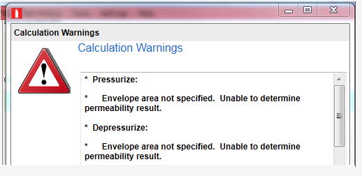
you can prevent it from coming up by modifying your settings.xml file.
You can find your settings.xml file in your MyDocuments/Retrotec/AppData directory. Open it using Notepad (you can right-click on the filename and choose “Open with” and then click on “Notepad”).
If you are using one of the NFPA standards, add the following text to the file: <Setting Name=”NFPAPermeabilityRefPa”>0</Setting>
When you are done it should look like:
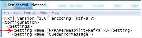
Choose File>>Save to save the Settings.xml file you just edited.
Start FanTestic Integrity and the error should not occur anymore.
If you are using one of the ISO standards, (or EN15004 or APSAD) add the following text to the Settings.xml file: <Setting Name=”ISOPermeabilityRefPa”>0</Setting>
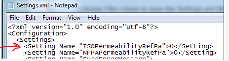
Choose File>>Save to save the Settings.xml file you just edited.
Start FanTestic Integrity and the error should not occur anymore.
NFPA and ISO do not certify any equipment or software directly. They are simply a standards writing body who takes input from the industry. In the case of hold time calculation and peak pressure evaluation the input from the industry was primarily from Colin Genge the CEO of Retrotec who wrote the original NFPA Enclosure Integrity Procedure for NFPA in 1984 and has been the only force in making changes to the Standards ever since. As a result, Retrotec training certification is accepted across all equipment manufacturers, end users in over 60 countries.
Colin Genge is used as a resource by Siemens, Tyco, Kidde, Ansul, Chemetron, Janus, Fike and 3M. If there is a question about enclosure hold time or peak pressure, he is the one who answers it.
Checking with Microsoft Windows Click Once Installer information, the error message you are receiving tells us the following:
“These are generic error messages that occur when the application cannot be started, and no other specific reason can be found. Frequently this means that the application is somehow corrupted during download, or that the ClickOnce store is corrupted.”
So it would seem that some of the files did not download correctly or that your ClickOnce user store may be corrupted.
Go to your Control Panel and Uninstall FanTestic. If you get a message box asking if you want to roll back to a previous state or to Uninstall, choose the Uninstall option. Then restart your computer. If there are any FanTestic shortcuts left on your desktop, you will need to delete them.
Install the latest version from the website:
https://retrotec.com/software.html
Restart your computer.
If after the install you get the same problem, then you need to clear your ClickOnce User store. You do that by doing the following:
“delete the contents of the following folder:
C:\Users\USERNAME\AppData\Local\Apps\2.0
Deleting these files will clear the information for all installed ClickOnce applications. They will re-install the next time their shortcut or URLs are used. “
If you cannot see the folder called AppData, you need to change two settings on your File Explorer 1) to allow you to see Hidden Files and Folders, and 2) to Show restricted System Files and Folders. You do this in the Organize dropdown, in the Folder and Search Options dialog.
Then you will need to Install FanTestic again from the website. If you have other ClickOnce installed programs, be sure to re- install them as well before you disconnect from the Internet. (all Retrotec programs are ClickOnce installed)
The leakage rate IS important because there is a direct correlation between leakage area and peak pressure. If the leakage is small enough, every room will face destruction upon discharge. The reality is that most rooms are so leaky that the opposite is a problem. The agent typically leaks out so quickly that the enclosure doesn’t pass the hold time requirements which means there is very little peak pressure which is why many systems do not require venting. For most FM200 systems there is a leakage range where the enclosure is tight enough to maintain sufficient hold time but not leaky enough to require vents. You’ll only know if you’re in that zone by performing a door fan test according to Annex C of NFPA 2001. ISO has a near identical Annex E.
Both Standards require a peak pressure evaluation to determine whether or not the enclosure will be damaged upon discharge. Unfortunately neither standard provides the peak pressure formula. Traditionally, manufacturers of inert systems have provided the necessary formula but none supplied them for halocarbons (chemical agents). A four year study of peak pressure at Fike which I was a lead participant with the involvement of Kidde Fenwal, 3M, DuPont and every other major player, determined that the inert formula in current use under-predicted peak pressure for inerts by 50%. We also uncovered the peak pressure characteristics for all the halocarbons which were reviewed by Joe Senecal, hear researcher at Kidde Fenwal and have since been published under FSSA and FIA’s name. Other equations in common use are VdS and the FIA inert formula for which I have never seen any data. In the case of VdS halocarbon formula, they don’t even predict negative peak pressures at all so are most likely based on theory only. I believe the FSSA formulae are correct since I have personally taken the data which has all been made public. No other data has been made public. Still, some insist on using VdS data because it requires smaller vents.
In every case the installer or testing agency must measure the leakage of the enclosure. From that value the hold time is determined using the ISO or NFPA standard. The peak pressure must also be calculated from this leakage value. In Europe, they typically do not rely on room leaks for peak pressure relief and install a vent large enough to vent the enclosure even though it may not be needed. Their theory is that accidental enclosure leaks might get sealed up but in reality they never do.
The second reason for not taking enclosure leaks into account is that in the design phase, the accidental leakage cannot be known. While this is true, the other is that enclosures must be extensively sealed at great cost of money and time to get them tight enough to pass the hold time evaluation so the air sealing can simply be stopped when the optimum hold time is reached. What actually happens in Europe, is that expensive air sealing is undertaken then a large pressure relief vent it added to put leakage back in. Even though this might appear to make little sense, there is some value in that the enclosure will be tighter with respect to smoke migration into the enclosure, temperature and humidity will be easier to control as will dust infiltration.
Just using an equation to determine peak pressure and putting in a vent to satisfy free venting is not enough.
Simply relying on vent manufacturers free vent area rating is insufficient because some are overstated since they do not open at a low enough pressure and for others the venting path is blocked, meaning there might be a vent there but there are other restrictions that reduce the vents effectiveness. The only sure way is to measure the free vent area in the enclosure directly using a door fan.
Pressure Relief Vents (PRVs) must also be checked upon installation and regularly thereafter that they actually open at the prescribed pressure and open in the correct direction. Many are installed backwards and have little value.
The reason why more enclosures have not been damaged is that they will take well over 1000 Pa in most cases without a problem and the enclosures themselves are usually too leaky to contain pressure in any case.
A properly tested system must have the enclosure tested with a door fan to determine hold time and peak pressure. Well over 90% of all the enclosures out there use Retrotec’s FanTestic Integrity to perform this function and for use as a design tool. We invented this type of testing and have spent 1000s of hours of our own time in research and understand every aspect of enclosure design from a peak pressure and hold time perspective. We support over 4000 enclosure testers worldwide and have responsibly maintained both standards’ enclosure testing annexes since 1984 for NFPA and a few years later for ISO. Most of the major manufacturers of agents and systems rely on our knowledge for normal and abnormal situations and we welcome your support questions whether you are a customer of ours or not.
Why is there a reference pressure for EqLA results?
(Or Flow, Permeability, ACH results?)
The results are all referenced to a single pressure, the reference pressure. The reference pressure is dictated by the standard with which the test is trying to comply.
Induced building pressure is directly proportional to airflow rate through a building, and EqLA is directly proportional to airflow rate; so that a higher induced building pressure would be a higher EqLA. Hence, there needs to be a reference pressure when referring to a leakage or flow result.
For the ASTM standard, the leakage result is required to be at a reference pressure of 50 Pa, whereas it is 75 Pa for the USACE standard. Reference pressure also applies to permeability (e.g. CFM/ft2) and air change (ACH) results.